 AI
AI
Proof of Concept with Commercial Off-the-Shelf Boards
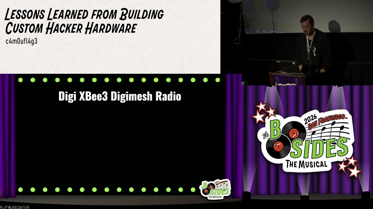
The Trinket M0 cost $10 and fit inside a keyboard. The Arduino Nano 33 IoT added multiple serial lines and BLE for $25. Both ran the SAMD21 chip, cheap at 80 cents and low-power at 3.3V. The SparkFun XB3 board added an XBee DigiMesh radio for $60, enabling mesh networking with up to 1,000 nodes. These COTS components proved the concept could work. Fischer and co-creator Jeremy Miller defined five goals: use less common protocols, be difficult to identify, maintain longevity, keep full ownership of firmware and data, and scale from a single PC to an entire office complex.
Fixing the Half-Second Lag and the Accidental UART
A half-second lag between typing and on-screen output would blow any covert implant. The extender board handled both BLE and XBee communication, overloading the processor. Adding a second Arduino Nano to offload BLE fixed the lag. Then the SparkFun board refused to talk UART to the Arduino. After hours of debugging, Jeremy wired the clock pin to ground by mistake, pulling it low and making UART work. SparkFun engineers said it was impossible. Fischer replied, “We have UART. You don’t.”
Dropping BLE, Adding Storage, and Surviving the Chip Shortage
BLE is common and easily sniffed by any smartphone. Fischer removed it. A micro SD card gave the implant a week of offline keystroke storage. To shrink the footprint, he proved he could work with raw SAMD21 chips using a test socket and SparkFun bootloader. The chip shortage hit. Microchip’s programming service lead times stretched over a year. Fischer started harvesting SAMD21 chips from $10 Trinket M0 boards by desoldering. An eBay seller eventually agreed to build a production run for Defcon.
Custom PCB Design: From Schematic to Solder Paste Struggles
Fischer used EasyEDA, starting from the open-source Arduino Nano schematic. He chose TQFP-44 chip packaging for hand-soldering with a soldering iron. The first PCB placed chips on both sides, causing one to fall off when the other side was heated. Serial polarity between the radio and microcontroller was wired incorrectly, requiring a second board order. A $100 digital microscope revealed what he was doing. The final revision moved all components to one side and switched to a header-style radio connector, enabling field-swappable radio hats.
Final Board Released, Then Open Sourced
The manufacturer delivered boards for Defcon 30, then went dark the day after. Fischer open-sourced the design. He added mounting holes for 3D-printed cases and removed header pins for SWD connectors on top. The radio hat connector, a happy accident from the chip shortage, allowed swapping radios in the field. Fischer’s advice: “Don’t cheap out. Just go buy yourself a digital microscope.” And read the manual – every component’s recommended circuit matters.
Notable Quotes
“Jeremy, you put the wires on the wrong side of the board.” c4m0ufl4g3 · ▶ Watch 18:01
“In the physical universe as we know it, there’s no way that that would ever work. You’re imagining things.” c4m0ufl4g3 · ▶ Watch 18:36
“We have UART. You don’t.” c4m0ufl4g3 · ▶ Watch 18:55
“Don’t cheap out. Just go buy yourself a digital microscope if you don’t have one.” c4m0ufl4g3 · ▶ Watch 40:19
“I learned that I did not have the polarity of my serial communication line between the microcontrollers correct.” c4m0ufl4g3 · ▶ Watch 40:57
Key Takeaways
- Start with COTS boards to prove the concept before investing in custom PCBs.
- A half-second lag can kill an implant; offload processing to separate boards.
- Accidental wiring hacks can work; document and open-source for repeatability.
- The chip shortage forced creative sourcing – desoldering $10 boards was a lifeline.
- Read the manual for every component’s recommended circuit to avoid reorders.